You can model features in the Sheet Metal environment that are manufactured with metal deformation techniques, such as deep drawing and coining. When parts are manufactured using deformation techniques, material thinning typically occurs. In Solid Edge, this material thinning is ignored and deformation features are constructed using the same material thickness specified for the model.
Like a jog feature, a louver feature is constructed using a single, linear element.
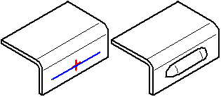
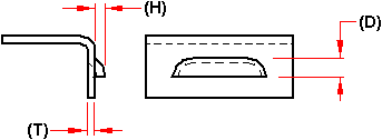
When constructing a louver, the louver height (H) must be equal to or less than the louver depth (D) minus the material thickness (T).
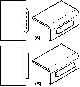
You can also specify whether you want the louver ends formed (A) or lanced (B) using the Louver Options dialog box.
Louver features cannot be flattened.
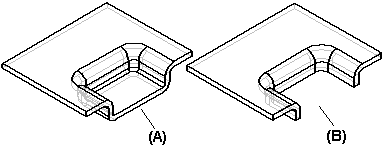
You can construct a drawn cutout using an open profile (A) or a closed profile (B).
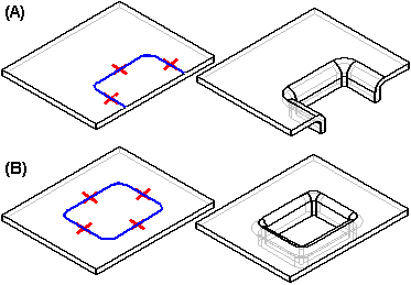
The ends of an open profile must theoretically intersect a part edge. A closed profile cannot touch any part edges. A drawn cutout can be constructed only on a planar face. You can use the Drawn Cutout Options dialog box to specify punch radius, die radius, and taper options.
When you draw the profile for a drawn cutout without arcs, you also can specify whether the corners are mitered (A), or rounded (B) using the Automatically Round Profile Corners option on the Drawn Cutout Options dialog box.

When you construct a drawn cutout, the sidewalls are constructed such that they lie inside the profile (A). After the feature is constructed, you can use the options to specify that the sidewalls lie outside the profile (B).

Drawn cutouts cannot be flattened.
Constructing a dimple is just like constructing a drawn cutout. The principal difference between the two features is that a dimple has a "bottom" (A), and a drawn cutout (B) does not.
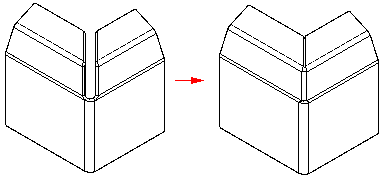
The Close 2–Bend Corner command modifies two flanges in one operation to close a corner where two flanges meet.
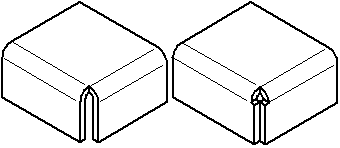
In the ordered environment, the Close 3-Bend Corner command closes corners that contain three bends.
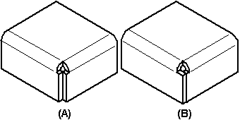
A closed corner is a treatment feature. You do not have to draw a profile, just select the edges you want to modify. With 2-bend corners, you can specify whether to close the corner (A), or overlap the corner (B).
Note:
The Overlap option is not available for 3-bend corners.
When you close the corner, you can also specify what type of bend treatment you want. For example, you can specify that you want a circular cutout applied to the bent faces.
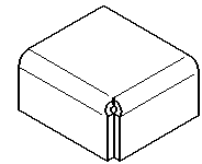
When you overlap a corner, select the bend to be overlapped.
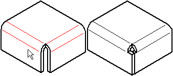
In the ordered environment, when you overlap a corner, you can use the Overlap Ratio option to compute the overlap as a percentage of the global material thickness.
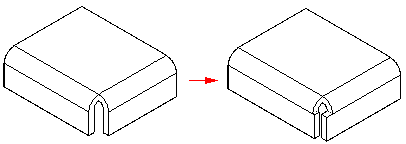
Note:
It is best to apply bend and corner relief before using the Close 2–Bends Corner command, so there is a clean corner to close. The corner should be symmetric, with equal bend radii and bend angles on the adjacent flanges. If there is more than one way to close the corner, edit the flanges themselves to close the corner the way you want.
You can construct a bead with an open sketch element,

or closed sketch region.

When constructing a bead profile using multiple elements, the element must be a continuous set of tangent elements.

You can also construct a bead feature using multiple, separate sketch elements. Each element must be a continuous set of tangent elements, but the profiles can cross each other.

You can select more than one sketch element to construct multiple beads in a single operation.
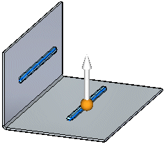
You can use the direction arrow to change the direction of the beads.
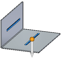
All disjoint beads created in a single operation offset to the same side.
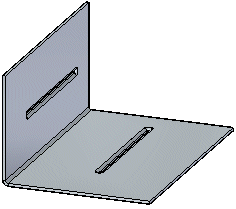
When constructing multiple disjoint beads, an entry in PathFinder, a feature profile, and a nail is created for each disjoint bead. Beads cannot be flattened and they cannot cross a bend.
You can specify the shape of the bead cross section and the type of end condition treatment you want using the Bead Options dialog box. For example, you can specify whether the bead shape is circular, U-shaped, or V-shaped. You can also specify whether the ends of the bead are formed, lanced, or punched.
You can use the Gusset command to add support across a bend. In the synchronous environment, you can construct gussets automatically across a bend. In the ordered environment, you can either construct gussets automatically or you can construct them from a drawn profile.
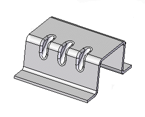
Note:
Gussets are not displayed in the flat pattern representation or in drawing views of the flat pattern in the Draft environment.
You can use the Gusset Options dialog box to specify the definition of the gusset. You can control such things as the shape of the gusset, the width and taper angle of the gusset, and the punch and die radius if the gusset is rounded. You can also use the dialog box to specify if the gusset is created automatically or from a user-drawn profile.
Select the Automatic Profile option on the Gusset Options dialog box to automatically create a gusset. Once you select a bend, the gusset profile is automatically displayed along the bend.
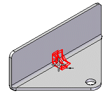
You can then click a keypoint to place the gusset,
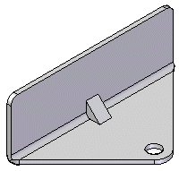
or, use the Pattern Type option to specify whether you want to place one gusset or a pattern of gussets. For example, you can use the Fit option to place three gussets that are equally spaced along the selected edge.
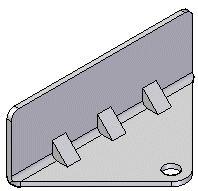
Select the User—Drawn Profile option on the Gusset Options dialog box to use a drawn profile to create a gusset. The profile can be an existing sketch or you can draw the profile while in the Draw Profile step.
To create a gusset from a user-drawn profile:
Click a keypoint to create a plane on which you want to draw the profile.
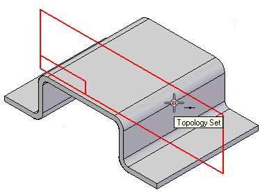
Note:
You may select an existing sketch to define the gusset profile and skip to step 3.
Draw the profile.
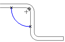
Click to define the direction of the gusset.
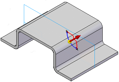
Click Finish to place the gusset.
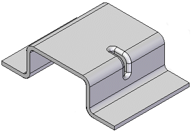
When using the User-Drawn Profile option, you can also you can draw a profile that constructs a gusset across two bends,
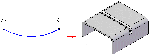
or, across a non-linear bend.
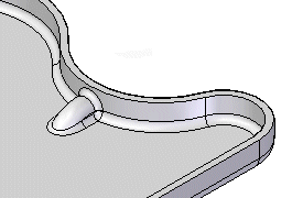
In the ordered environment, you can use the Cross Brake command to stiffen a sheet metal panel. The command creates a set of bends from a sketch that is coincident to the sheet metal part face.
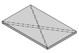
A cross brake feature does not deform the 3D model. It adds attributes containing information about the bends. This attribute information is used when creating a flat pattern or drawing of the sheet metal part.
To create a cross brake feature:
Select the face on which you want to construct the cross brake.
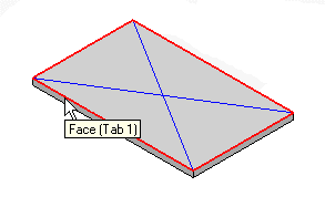
Select the sketch(es) you want to use to construct the cross brake.
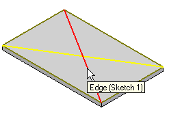
Specify the bend angle and direction for the cross brake.
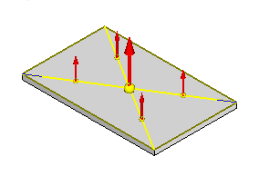
Click Finish to construct the cross brake.
