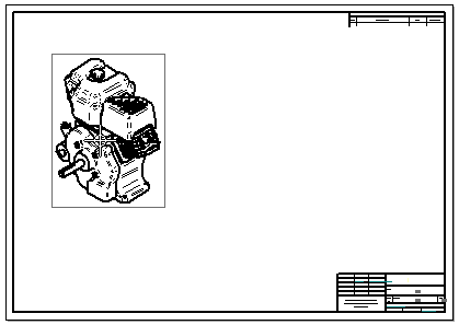
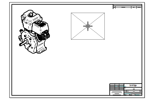
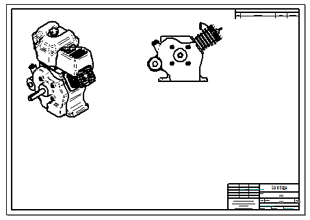
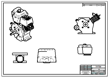
You can use the View Wizard to create a drawing that shows an assembly along with views of one or more of its individual parts.
Choose Home tab→Drawing Views group→View Wizard  .
.
(Select a model) Do one of the following:
In the Select Model dialog box, select an assembly document (.asm), and then click Open.
Tip:
You can apply a predefined display configuration to the model using the Configuration list in the Select Model dialog box.
In the Library docking window pane, browse to an assembly document, and then drag it from the Library onto the drawing sheet.
The View Wizard command bar is displayed, and a preview of the model view is shown on the sheet. The default drawing view orientation is based on the type of model you selected and the drawing template you are using.
Example:
For an assembly model, an isometric drawing view is created. This example shows a VHL preview of the assembly view using dynamic display mode.

(Place the primary view) Select the drawing view formatting options on the View Wizard command bar that you want to apply, and then move the view where you want it on the sheet and click.
(Place another view showing an assembly part) Do the following:
Select the View Wizard command again.
In the Select Attachment dialog box, select an assembly part and click OK to continue.
A preview showing the extent of the drawing view is displayed on the sheet. If the view is too large or small, select a different drawing view scale using the Scale list on the command bar.

Move the drawing view preview where you want to place it and click.

Repeat the previous step to select and place views of other parts in the assembly.

Press Esc.
Tip:
To display assembly material removal features in the drawing view--holes, chamfers, and cutouts--you can select the Show assembly features check box in the Drawing View Creation Wizard (Drawing View Options).
To control the display of material addition features, such as fillet welds and protrusions, you can use the options on the Display tab (Drawing View Properties dialog box). You also can define a display configuration in the assembly with material addition features hidden, then use the display configuration when placing a drawing view of the assembly.
Before you click to place a drawing view, you can change the drawing view direction and orientation using either of the following options on the View Wizard command bar:
Click Drawing View Layout  , and then select the Custom button in the Drawing View Creation Wizard (Drawing View Layout). This displays the part view in the Custom Orientation dialog box, where you can choose a default or custom view orientation, rotate the model, and align the model to a face or an edge to an axis. You also can create a perspective drawing view.
Click View Direction  , and then select a default view or a named view from the list.
To enhance the performance of assembly drawing views, you can clear the Show Hidden Edges and Show Edges of Hidden Parts options in the Drawing View Creation Wizard (Drawing View Options). Changing these settings only affects the current drawing view you are creating.
To apply these changes to all assembly drawing views, clear the Show Hidden Edges and Show Edges of Hidden Parts options on the Edge Display tab (Solid Edge Options dialog box). You can create a draft template file with these options cleared and use it to create all the drawing views of your assemblies without hidden lines.