The Custom Orientation dialog box provides view manipulation options for the primary view of the 3D part or assembly that is selected in the Drawing View Creation Wizard (Drawing View Layout). You can use the controls in the dialog box to reorient the primary 3D part.
When you finish reorienting the part and close the dialog box, the Drawing View Wizard is displayed for you to select additional view orientations to place with the primary view.
Activate Part
Activates (loads into memory) the model data associated with a part. This enables you to use a face or edge on the part for precise placement of the view before the view is created. Activate Part is only available with assemblies.
Shaded with VHL Overlay
Specifies if the view will be simply shaded or shaded with VHL overlay. Using the Shaded with VHL Overlay may decrease your performance when working with large assemblies.
View Orientation 
Displays a list of Solid Edge default views and applies the selected view orientation to the current model. The default view options include Front View, Top View, Right View, Iso View, and Trimetric View. As you move your cursor down the list of default views, you can see a live preview of the view orientation applied to the model.
Note:
You also can use keyboard shortcut keys to apply a view orientation to the model and to fit the model contents to the active window. For more information, see the View Orientation command.
Named Views
Applies a user-defined Named View override to the current model view orientation. Named Views are created using the View Orientation command in the Part, Sheet Metal, and Assembly environments
Rotate
Rotates a view freely about one of the following:
The center of the view
Any one of three principal axes
Any edge of the model
Note:
You also can adjust the model orientation by pressing the left mouse button as you move the mouse.
You can press the Home key to rotate the model to the default isometric view.
Spin About
Rotates a view normal to a face. Spin About is not available for assemblies.
Common Views
Selects one of six principal views or eight isometric views. You can use the arrows on the displayed dialog box to select the view.
Look At Face
Defines a view using any planar face. Look at Face is not available for assemblies.
Align Edge
Aligns a view to a linear edge. In cases where Look At Face does not align the view the way you want, you can use this option to select a linear edge of the model and specify a new x or y axis.
Zoom Area
Zooms into an area in the window. The two points you place define the view.
Zoom
Reduces or enlarges the display of geometry around a specified point in the window.
Fit
Fits all elements to the window.
Pan
Enables you to move in any direction from a specific point on the model to see other areas of the model.
Perspective
Applies perspective to, or removes perspective from, the view in the Custom Orientation window. A perspective view appears more realistic than an isometric view. When perspective is applied, objects that are farther away appear smaller.
When you select the Perspective option, you can choose a predefined angle from the Perspective Angle list, or you can define a custom perspective angle using Shift+Ctrl while rotating the mouse wheel.
Perspective Angle
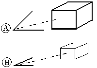
When the Perspective option is selected, you can choose from a list of perspective angle values that equate to the focal lengths of a 35 mm camera. As the angle increases, the distance to the object decreases, making the object appear closer. For example, the angle in the first picture (A) is wider than the angle in the second (B), so that the first picture appears closer.

Portrait (85 mm)
Normal (50 mm)
Wide (35 mm)
Very wide (10 mm)
Custom--This value is set and applied automatically when you press Ctrl+Shift while you rotate the mouse wheel to change the perspective view angle and distance.
Rotation Angle
Specifies the angle of rotation.
Close
Closes the Custom Orientation dialog box and displays the Drawing View Wizard for you to continue selecting the drawing view layout.