Sets options for a drawing view. This command bar is displayed after a drawing view border is selected. Not all options are available for all drawing views.
Drawing View Style
Displays the name of the currently used drawing view style, or applies a different drawing view style.
Show Caption
Selects the captions to display for the currently selected drawing view or view annotation, according to the currently selected Drawing View Style.
Show Primary Caption
Displays the content defined for the Primary caption in the Caption tab (Drawing View Style dialog box).
Show Secondary Caption
Displays the content defined for the Secondary caption in the Caption tab (Drawing View Style dialog box).
You also can choose whether to show the following information, if it is defined in the caption text on the Caption tab (Drawing View Style dialog box) for the currently selected drawing view style:
Show Suffix
When a section view, detail view, or auxiliary view is selected, displays the caption suffix.
The suffix can be displayed in the caption when %AS is added to the primary or secondary caption text, and when the View Annotation Name property text code (%VA) is added to the Suffix Property box.
Show Annotation Sheet Number
Displays the sheet number of the view annotation—the cutting plane, viewing plane, or detail envelope—when %LN is added to the primary or secondary caption text, and when the appropriate property text string is added to the Annotation Sheet Number (%LN) Property box.
Show View Scale
Displays the view scale in the caption when %VS is added to the primary or secondary caption text, and when the appropriate property text string is added to the View Scale (%VS) Property box.
Show Angle of Rotation
Displays the view rotation angle in the caption when %VR is added to the primary or secondary caption text, and when the appropriate property text string is added to the Angle of Rotation (%VR) Property box.
Note:
Primary captions, secondary captions, and view annotation captions are defined in the Drawing View Style dialog box. To learn how to create captions for selection on the drawing, see these Help topics.
Scale
Specifies the drawing scale as a standard ratio. The specified ratio defines the size of the drawing in relation to the size of the real-world object. For a 2:1 ratio, the 2 represents the size of the drawing and the 1 represents the size of the real-world object.
Scale Value
Specifies a custom scale value.
Show Annotation
Specifies whether to display the view annotation graphics, such as the cutting plane, detail envelope, or viewing plane. Also specifies whether to display the profiles for a broken-out section view for the selected drawing view. Displaying the profiles allows you to edit the profile for a broken-out section view.
This option is available only when the selected view is the source view where the view annotation graphics are drawn.
Properties
Displays the Drawing View Properties dialog box.
Modify Drawing View Boundary
While you can modify the size of a rectangular drawing view cropping boundary simply by dragging its handles, the Modify Drawing View Boundary option allows you to define a custom, non-rectangular drawing view cropping boundary. This option is not available for dependent and independent detail views.
When you select this option, the drawing view is displayed in a special cropping window. The rectangular boundary is converted to four endpoint connected line segments. You can use the 2D drawing tools to redraw the view cropping border. However, the new cropping boundary profile must be closed.
To use a portion of the rectangular boundary window in the custom profile, draw new line segments that connect to the existing line segments. When you're done drawing the boundary, use the Trim command to remove the unneeded line segments.
To draw a new boundary profile from scratch, delete all the existing line segments and then draw the new boundary using the 2D drawing tools.
Use the Close Cropping Boundary button on the ribbon to exit the cropping window, update the view, and return to the drawing.
Click here to see illustrations showing how the Modify Drawing View Boundary option can be used to create a custom cropped drawing view.
You can return a cropped drawing view to its original display using the Uncrop command on the selected drawing view's shortcut menu.
Shading Options
Specifies color, grayscale, shading, and edge visibility for the drawing view.
Not Shaded
Displays color with visible and hidden edges, but no shading.
Shaded
Displays color and shading, but no edges.
Shaded with Edges
Displays color and shading with visible edges.
Grayscale Shaded
Displays grayscale and shading, but no edges.
Grayscale Shaded with Edges
Displays grayscale with visible edges.
Show Broken View
Shows or hides the broken view regions of the drawing view.
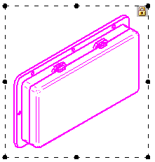
 Lock drawing view position
Prevents the selected drawing views from being moved accidentally. When this box is checked, and the drawing view is highlighted, a lock symbol is displayed within the drawing view boundary to indicate its position is fixed.
A locked drawing view still can be moved using explicit commands. To learn more, see Drawing view manipulation.
