The Connector command bar is displayed when you select the Connector command and when you select an existing connector in the document.
Dimension Style Mapping
Specifies that the annotation style selected for Connectors on the Dimension Style tab of the Solid Edge Options dialog box determines the style for connectors placed in the drawing. When you set this option, the Connector Style option is not available.
Style
Lists and applies the available styles. This control is not available when Connector Dimension Style Mapping is enabled.
Line Color
Specifies connector line segment color.
Line Type
Specifies connector line segment type.
Line Width
Specifies connector line segment width.
Shape
Select connector shape from the pull-down list, or press the S key to change the shape of the selected connector. Connector shape options are depicted in the command bar: The connector shape is drawn between two 2D elements, objects, or blocks at two points. The start and end connector handles mark the location of these two points.
The Jump and Step connectors also have a middle handle. The Handle Usage column in the table below describes how this handle can be used.
All but one of these shapes can be flipped during or after placement using the Flip button or the F key on the keyboard.
These examples show the connector shape as depicted in the command bar, in which the start handle is red and the end handle is green.
|
Shape |
Default Orientation |
After Flip |
Handle Usage |
|
Line |
|
Not Applicable |
|
|
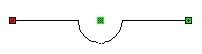
Jump |
|
|
After placement, select middle handle to: -Snap to a grid -Drag to relocate the arc along the line segment -Connect to (be driven by) another connector line segment or line element -Another connector can connect to it (drives other connector location). |
|
Corner |
|
|
|
|
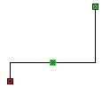
Step |
|
|
After placement, select middle handle to: -Snap to a grid -Drag to relocate the arc along the line segment -Another connector can connect to it (drives other connector location). |
|
Step (Edited to U-Shape) |
|
After placement, the middle handle at the step's center can be moved to create a U-shape. |
|
|
|
About Auto Flip - If you are connecting to a horizontal or vertical line element or connector with a corner or step connector, the corner/step connector will flip automatically so that the first segment of the connector being placed is collinear with the selected line or connector. You can reset the automatic flip using the manual Flip button or F key, and Solid Edge will retain this orientation until you restart the Connector command. |
||
Flip Orientation
When adding or editing jump, corner, or step connectors, changes the orientation of the connector shape. Alternatively, press the F key to flip the connector.
You can also use this feature to reset a corner or step connector that has been automatically flipped during placement.
Start Terminator
Specifies the shape of the start terminator. The start and end terminators can be different shapes to make them easily distinguishable on a drawing.
When set to Blank, no terminator will be used. Start terminator size can be set in the Connector Properties dialog box.
End Terminator
Specifies the shape of the end terminator. The start and end terminators can be different shapes to make them easily distinguishable on a drawing.
When set to Blank, no terminator will be used. End terminator size can be set in the Connector Properties dialog box.
Jump Radius
Sets the size of the jump arc radius as a multiple of the text height. The default value is 0.5. If you change the value for a connector you are editing, press Enter to update the display.